JXT6966
JXT6966 Single Board Computer

Key Features
- Dual Multi-Core Processors
- DDR3-1300 Memory Interfaces
- PCI Express 2.0 Interface Links
- Extensive Device I/O Options
The JXT6966 Single Board Computer
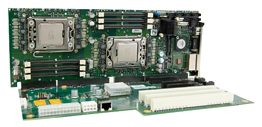
The JXT6966 single board computer is a dual-processor PICMG 1.3 SBC featuring Intel® Xeon® C5500 processors and support for PCI Express 2.0 I/O cards. This single board computer supports DDR3-1333 Mini-DIMMs and maximum system memory capacity of up to 48GB. The JXT6966 SBC features SATA/300 ports, multiple I/O and communication interfaces including PCI Express 2.0.
The SBC’s flexible I/O system design is driven by the PCIe 2.0 processor links and the Intel® 3420 Platform Controller Hub (PCH). The external I/O card interfaces adapt to PCIe 3.0, PCIe 2.0/2.1 and PCIe 1.1 plug-in cards with either a x16, x8, x4 or x1 PCI Express edge connector.
An additional PCI Express 2.0 x16 link expansion is available using the optional PEX10 module on the BXT7059 SBC. The six-channel, DDR3-1333 memory interfaces feature DDR3 Mini-DIMM technology, while the SBC’s three Gigabit Ethernet LAN interfaces, including a PICMG 1.3 backplane LAN, ease many system communication challenges.
Key features of the JXT6966 single board computer include:
- Power-saving SBC design using the Intel® 3420 Platform Controller Hub (PCH)
- Six-channel, DDR3-1333 memory interfaces feature DDR3 Mini-DIMM technology
- Flexible PCIe Gen 2 / PCIe Gen 1.1 interfaces support x16, x8, x4 and x1 PCI Express cards
- Three Gigabit Ethernet LAN interfaces including a PICMG 1.3 backplane LAN
- Supports additional x16 PCI Express 2.0 link expansion with PEX10 module
- Enhanced SBC stability and component protection provided by full-length stiffener bars
- Processor options support Intel® Virtualization Technology
In addition, BIOS flexibility is built in by offering various BIOS modifications that may be needed to meet unique system requirements and maintains strict revision control for custom BIOS variations. The JXT6966 is designed, manufactured and supported in the U.S. and is covered by our exclusive five-year factory warranty.
Tech Specs
Model Number
JXT6966
Form Factor
PICMG® 1.3 Form Factor – Automatically adapts to graphics or server-class backplane PCIe link configurations – one x16 and one x4/four x1 or two x8 and one x4/four x1 PCIe links
2 – Intel Xeon C5500 Series
Processors
Two Quad-Core Intel® Xeon® Processors EC5549 (2.53GHz with Hyper-Threading, 8MB Cache)
Two Dual-Core Intel® Xeon® Processors EC5539 (2.27GHz without Hyper-Threading, 4MB)
Two Quad-Core Intel® Xeon® Processors EC5509 (2.0GHz without Hyper-Threading, 8MB)
Two Quad-Core Intel® Xeon® Processors LC5528 (2.13GHz with Hyper-Threading, 8MB)
Jasper Forest processors support Intel® VT-x2 and Intel® VT-d2
BIOS (Flash)
AMI – Aptio® 4.x
Chipset
Intel® 3420 Platform Controller Hub (PCH)
Configuration
DDR3-1333, 48GB max.
Comms
1 – x16 and one x4 or two x8 PCIe links (2.0/1.1) and one x4 PCIe 1.1 link (Edge connectors A&B)
1 – x16 PCIe link (2.0/1.1) via PEX10
2 – 10/100/1000Base-T (I/O Bracket)
1 – 10/100/1000 (Edge conn. C)
I/O
6 – SATA/300 ports with RAID
8 – USB interfaces
1 – VGA Analog Video
1 – IOB33 1 – PEX10
Memory
192GB (max. theoretical) and 48GB max. using 8GB DDR3 Mini-DIMMs, six-channel DDR3 (DDR3-1333) interface with six Mini-DIMM sockets (3 per CPU)
PCI Express Edge Card Interfaces
Standard PICMG 1.3 PCI Express Interfaces – Automatically adapts to graphics or server-class backplane PCIe link configurations – one x16 and one x4 or two x8 and one x4/ PCIe links. The direct PCIe links from the board’s processors (links A0, A1, A2 and A3) may operate as either PCIe Gen 1.1 or PCIe Gen 2.0 depending on the backplane design. The x4 link from the board’s PCH (link B0) is always a PCIe 1.1 link regardless of what is connected to this link and the option card that is used. PCIe link (B0) from the board’s PCH has a x4 default configuration and can be made to bifurcate into four, x1 PCIe links with a factory modification to the JXT6966 board. Contact us if you require this B0 link configuration change. The optional x1 link available with an IOB33 expansion module is a PCIe 1.1 link only.
Optional PCI Express Gen 2.0 Link Expansion – Installing a PEX10; PCI Express Expansion module, on the back of the JXT6966 provides four additional x4 PCIe Gen 2 links to a PCIe backplane like the BPC7009. The backplane must have an edge connector slot to accommodate the PEX10′s edge connector. The backplane may use these additional x4 links independently or as one additional x16 PCIe Gen 2 link.
Video Interface
XGI® Volari™ Z11M Graphics Processing Unit, 8MB video memory supports screen resolutions up to 1920 x 1200 (WUXGA) with a 64K color depth
Ethernet Interfaces
Intel® 82575 Ethernet Controller – Two 10/100/1000Base-T on I/O Bracket Connectors
Intel® 82577LM Ethernet PHY – One 10/100/1000Base-T interface routed to SHB edge connector “C”
On-Board Interfaces
Eight USB 2.0 ports – Two each on the I/O bracket and on-board headers plus four routed to SHB edge connector “C”
Six SATA II/300 interfaces with RAID 0,1,5 and 10 support
Optional IOB33 provides the following I/O expansion capabilities:
– IOB33 I/O plate connectors
– Two DB9 RS232 serial ports and one PS/2 MiniDin for PS/2 mouse & keyboard
– IOB33 header connectors
– Floppy drive, parallel port, PS/2 keyboard and PS/2 mouse
Watchdog Timer
The JXT6966 provides a programmable watchdog timer with programmable timeout periods of 100 msec, 1 second, 10 seconds or 1 minute via board component U13. When enabled the WDT (U13) will generate a system reset. WDT control is supplied via the General Purpose IO pins from the Intel® 3420 Platform Controller Hub (PCH). The PCH’s GPIO_LVL2 register controls the state of each GPIO signal. This 32-bit register is located within GPIO IO spaces. The GPIO_BASE IO address is determined by the values programmed into the PCH’s LPC Bridge PCI configuration at offset 48-4B(h).
See the watchdog timer section in the specifications chapter of the JXT6966 Hardware Manual for more detailed information and a WDT programming example.
Battery
Lithium – CMOS data retention
Mechanical
Board dimensions – 13.330” (33.86cm) L x 4.976” (12.64”cm) H
Standard cooling solution height – 2.15” (54.61mm)
Agency Approvals and Compliance
Designed for UL69050, CAN/CSA C22.2 No.60950-00, EN55022:1998 Class B, EN61000-4-2:1995, EN61000-4-3:1997, EN61000-4-4:1995, EN61000-4-5:1995, EN61000-4-6:1996, EN61000-4-11:1994
Mean Time Between Failures (MTBF)
MTBF – 174,814 Power-On Hours (POH) at 40° C per Bellcore
Power Requirements – 100% stressed
Typical Values – 100% Stressed with various system memory capacities Dual-processor configuration
| CPU | Intel® No. | Memory | +5V | +12V | +3.3V |
|---|---|---|---|---|---|
| 2.53GHz | EC5549 | 12GB | 1.09A | 12.20A | 4.48A |
| 2.27GHz | EC5539 | 12GB | 0.92A | 9.78A | 4.48A |
| 2.13GHz | LC5528 | 12GB | 1.06A | 10.57A | 4.94A |
Power Requirements – Idle
Typical Values – Static Desktop (System Idle) with various system memory capacities Dual-processor configuration
| CPU | Intel® No. | Memory | +5V | +12V | +3.3V |
|---|---|---|---|---|---|
| 2.53GHz | EC5549 | 12GB | 1.07A | 6.48A | 4.44A |
| 2.27GHz | EC5539 | 12GB | 0.90A | 6.29A | 4.48A |
| 2.13GHz | LC5528 | 12GB | 1.06A | 4.87A | 4.91A |
Operating Temperature
0-50° C with standard cooling solution and 350LFM of continuous airflow
Environmental
Airflow: 350LFM continuous airflow
Storage: -20° to 70° C.
Humidity: 5% to 90% non-condensing.
Downloads
Hardware Manual for JXT6966 & JXTS6966, Quad-Core Intel® Xeon® C5500 Series Processors
BIOS Setup Manual for JXT6966 & JXTS6966 System Host Boards
Intel® PRO/1000 MT Network & Server Adapters for the Intel® 82575 Ethernet Controller (Dual GB LAN)
Intel® PRO/1000 MT Network & Server Adapters for the Intel® 82578 Ethernet PHY (Backplane LAN)
Video Driver for the XGI® Volari™ Embedded Z11 Graphics Processing Unit
Intel® SATA Raid Drivers for the Intel® 3420 PCH
Options
Single Board Computers

 IOB33 PCIe and IO Expansion Board
 PEX10 PCI Express Expansion Module